Industrial generators are helpful appliances that supply electricity during a power outage, preventing discontinuity of daily activities or disruption of business operations. However, it is crucial to understand that a generator does not actually ‘produce’ electricity. Instead, it is a device that converts mechanical energy obtained from an external source into electrical energy as the output.
To help you better understand the inner workings of a power generator, let us examine the primary components of this equipment and explore how they each function to enable a generator to work as intended.
The Main Components Of A Power Generator
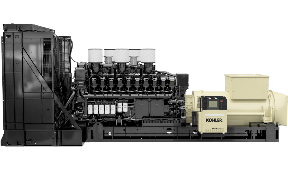
Component #1: Engine
The engine is responsible for converting latent energy from a fuel source into mechanical energy. Generally, the size of the engine is directly proportional to the maximum power output the generator can supply. As for the fuel source used in the engine, users will typically choose between gasoline, diesel, or gas.
With that said, diesel tends to be the most popular fuel choice for a backup power generator for several reasons. Firstly, as the most fuel-efficient of the three options, diesel-powered generators offer a higher power output while consuming less fuel, translating to lower costs. Moreover, diesel is usually more readily available and can tolerate harsh environments and heavy usage, making it more suited for industrial applications. Most importantly, it is less flammable, resulting in a safer work environment.
How Does A Diesel Engine Work?
Diesel engines operate on the principle of compression ignition, with the fuel being injected into the cylinder before the piston reaches the top of the stroke. As air is compressed in the engine cylinder, the temperature increases rapidly. With insufficient time for the heat to escape to the surrounding cylinder walls, the diesel fuel ignites spontaneously due to the high ambient temperature of the compressed air.
Due to the mechanism required to facilitate this setup, diesel engines are typically heavier duty than gaseous engines to handle the high cylinder compression (700 to 1200 p.s.i) and compression ratios (15:1 to 20:1). They are also segregated into two categories – naturally aspirated or forced induction. The former features air supplied solely on atmospheric pressure. Meanwhile, the latter contains pressurised air pushed into the engine using a turbocharger or supercharger.
Component #2: Alternator
The alternator is responsible for converting mechanical energy into electrical energy via electromagnetic coupling. Connected to the generator engine, it delivers the necessary power to rotate the alternator to produce electricity.
It contains an assembly of stationary and moving parts encased in a housing, such as the stator, rotor, excitation, and voltage regulator. These components work together to produce relative movement between the magnetic and electric fields, resulting in the generation of electricity.
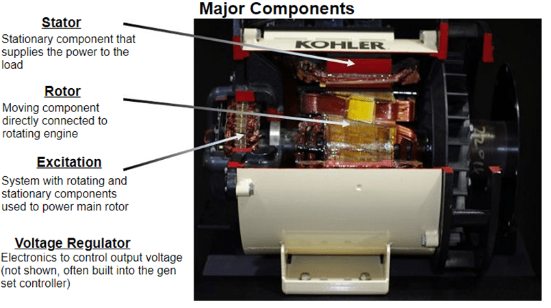
Please refer to the image above for a detailed breakdown of the various components present in an alternator. The stator is responsible for supplying the power to the load, while the rotor is connected directly to the rotating engine. Meanwhile, the excitation is a system comprising rotating and stationary parts used to power the main rotor.
Lastly, the voltage regulator, as the name implies, controls the output voltage of the generator and is often built into the genset controllers. When there are changes in the electrical load, the voltage regulator will detect it and adjust the output voltage accordingly to support the load.
Component #3: Cooling System
As with any equipment that generates power, heat will inevitably be produced as a result of the energy conversion process. Therefore, it is essential for any power generator to have an efficient cooling and ventilation system to withdraw heat and prevent it from damaging the various components within.
Regardless of the power generator-set installation, its cooling system generally utilises some type of heat exchanger to cool down the engine. This heat exchanger can come in the form of a radiator or shell and tube to transfer heat from one medium to another. For example, from air to air, liquid to air, or liquid to liquid.
Let us share the common examples of cooling systems featured in power generators below.
1. Jacket Water Cooling System (JW)
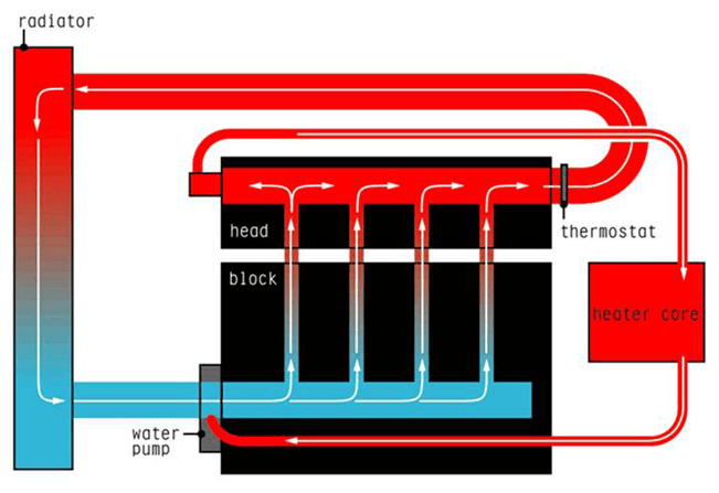
This cooling system typically utilises a combination of jacket water and an antifreeze mixture (coolant) to absorb and carry away heat from the engine. A water pump, driven by the engine’s crankshaft or a belt connected to it, will circulate the coolant through the system, removing heat from the various engine components and preventing them from overheating.
After absorbing the heat from the engine, the coolant flows to the radiator/heat exchanger, where the fin helps dissipate the heat from the coolant, lowering its temperature. The fins in term will be cooled by the radiator fan, which pulls in cool ambient air. Once cooled, the coolant returns to the engine through the water pump, repeating the cooling cycle until the engine reaches a stable temperature.
2. Charge Air Cooling (CAC)
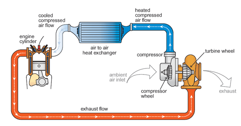
Unlike jacket water circuits, which circulate coolant through a water pump to remove heat from the engine, charge air cooling systems, also known as air-to-air aftercooling (ATAAC), utilise forced air to cool the turbocharged air before it enters the engine’s combustion chamber.
Heat is removed by transferring the heated compressed air through a radiator air-to-air heat exchanger, allowing it to cool before entering the engine to optimise power and performance. The goal is to lower the engine’s intake air temperature to improve emissions and output power efficiency.
3. Separate Circuit Charge Cooling (SCCC)
Separate circuit charge cooling, also referred to as separate circuit aftercooling (SCAC), utilises two engine-mounted water pumps, with each circuit pumped to an individual radiator core for cooling. One distributes jacket water in the normal manner, similar to a jacket water system. Meanwhile, the other is responsible for cooling the engine’s intake air after it has been pressurised by a turbocharger.
Heat is removed from the combustion air when it passes through the air-to-water engine-mounted aftercooler. Subsequently, the after-cooler heated liquid is cooled by circulating it through an air-to-water radiator/heat exchanger. By distributing cooling water through the aftercooler, the engine is able to operate more efficiently and produce more horsepower, optimising power and performance.
Set-Mounted Radiator Vs. Remote Radiator
Beyond the different cooling systems available, users must also decide between a set-mounted or remote radiator based on their generator room setup. Implementing the correct radiator will ensure it works as intended without issues. However, this decision depends on several factors, such as the generator room setup and ventilation airflow. Moreover, users should consider the various advantages and disadvantages of each application.
Set-mounted radiators are generally the more affordable and hassle-free option as they come pre-installed within the generator, saving on-site installation costs and time. Furthermore, no secondary power is necessary to kickstart the radiator. However, generators equipped with set-mounted radiators tend to have a larger footprint to accommodate this additional component. As a result, they cannot fit into compact genset rooms.
Conversely, remote radiators, as their name implies, are separate from the generator. As a result, users have the flexibility of installing this tool in a different location to save space in the genset room. Likewise, the absence of the radiator contributes to a smaller generator, so less room is required to store the equipment.
However, this feature also comes with its caveats. Since the radiator is separate from the generator, users must install this component separately. Additional piping and fittings are also required to connect the radiator to the generator, and a secondary energy source will be necessary to power the radiator.
As you can see, a generator features a complex mechanism comprising multiple components working in tandem to provide backup power in various residential and industrial applications. By understanding the intricate workings of these essential devices, you will be able to make an informed choice regarding your generator configurations, ensuring optimal performance and longevity, thus enhancing your business’s resilience in the face of power disruptions.
At Kohler, our power generators are built to power various applications, including hospitals, manufacturing facilities, data centres, airports, and more.